
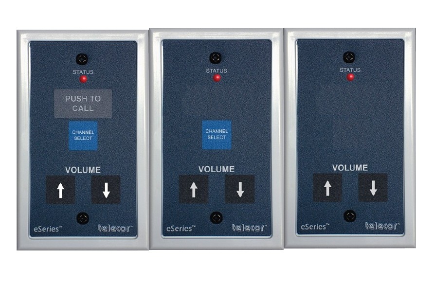
The eCS-4, eCS-5, and eCS-12 Volume Control and Public Channel Select Stations add separate smart volume controls to eSeries endpoint stations. These stations are designed to operate with a host device such as the eS8-TB-MA and eS8-TB4-MA talkback speakers, 2444(-LD) Message Display/Calendar Clock/Speaker(/Strobes), e365-TB-MA Message Display/Clocks, or eSBM-TB Speaker Breakout Modules. The eCS-5 and eCS-12, which have no call-in capabilities, also operate with the eS8-MA Ethernet Speaker. The eCS-4, eCS-5, and eCS-12 stations include volume up and volume down momentary contact touchpoints. These controls adjust the level of the audio program currently being distributed over the speaker. Separate user-set volume levels are maintained for normal priority pages, emergency priority pages, intercom calls, fault tones, and Public Channels.
The eCS-4 and eCS-5 stations are equipped with a channel select touchpoint to tune the speaker to a Public Channel–an audio source that is connected to an eAMP and plays continuously across the eSeries network. If the station is connected to a Message Display/Calendar Clock, pressing the Channel Select button will scroll the name of the Public Channel on the message display. The eCS-4 station also includes a touchpoint to initiate a “Normal” priority level call-in from a remote location. The station has a STATUS LED that provides call-in confirmation. When a call-in is placed, the LED flashes, confirming call-in placement. The LED continues to flash until the call-in is answered by the console operator. The eCS-5 and eCS-12 stations are designed to supplement other eCS call stations
capable of placing call-ins.
The eCS-4 Call Stations can also provide “Emergency” priority level call-ins by pressing the call touchpoint three times or pressing and holding the touchpoint for three seconds. All Telecor eCS stations can provide “message waiting” indications to staff members. If no one is present in a room to respond to a call, or the room is in Privacy or Do Not Disturb mode, the console operator will have the option to leave a Message Waiting (MW) indication. If the MW option is chosen, the STATUS LED indicator on the room eCS stations will begin to pulse. When a call-in is initiated from the room, the MW indication will be automatically deactivated, and the call-in will be automatically routed to the console that left the MW indication.
Call Stations are fully supervised and monitored for connectivity by the host device (Talkback Speaker, Message Display/Calendar Clock/Speaker or Message Display/Calendar Clock). If a wiring fault is detected between a Call Station and the host, the host will audibly and visually indicate the error. In addition, the Status LED on the station will pulse to indicate a trouble condition. The ePort, eLog, eCI, and eAmplifiers can also generate an alarm tone. The eCS-4 Call Station’s call-in destination is also monitored. If the device that is configured to receive the station’s call-in loses network connectivity, the host will automatically search for an alternate destination. If no other suitable call-in destinations exist, the host will audibly and visually indicate an error.
In the event of an open circuit, short circuit or short to ground, the Telecor System detects the fault and provides notifications automatically with a tone and fault LED indication on designated eAmplifiers, ePorts, eLogs or eCIs.
The STATUS LED on the eCS Stations also indicates the state of station readiness. A solid STATUS LED indicates the station is connected to a network and is ready. It also allows the call station to be found in the dark. A fast flashing STATUS LED indicates an active audio connection, a slow flashing STATUS LED indicates a network problem, and a STATUS LED that is off indicates that the station is unpowered and is inoperable.
The eCS station surface consists of a laminated mylar membrane that is water resistant and allows for easy cleaning. Designed for flush wall mounting, it is installed onto a standard one-gang backbox with 3-9/32" mounting centers. All connections to field wiring are accomplished with RJ-45 connectors.